Active Bandpass Filter Circuit Diagram
Active band pass filter – all about electronics How to build single op-amp bandpass filter Active dual two-stage bandpass filter circuit
Band Pass Filter: Circuit Diagram, Types, Calculator and Its Applications
Basics of bandpass filters Filter bandpass circuit active gain diagram seekic db basic Band pass filter circuit design
Filter pass band circuit diagram wide transfer function active passive electrical4u
Filter bandpass active audio calculate inputVariable bandwidth bandpass active filter circuit Active_adjustable_bandpass_audio_filterActive band pass filter circuit diagram and its frequency response.
Active band pass filter circuit design and applicationsFilter circuit active diagram seekic bandpass author published 2009 Pass filter band circuit wide low diagram bandpass which segments normally intended dropping act different simple wellFrequency passive 3db order circuit bpf bandpass bode pasa paso guinguette pentingnya apa bedeutung.
Active_second_order_bandpass_filter_for_speech_range
Calculate bandpass active filterCircuit bandpass active dual stage filter two seekic 1khz frequency shown figure center Circuit filter order second diagram bandpass active range speech seekic op amp hz lm1458Bandpass magnitude.
Bandpass filter oscillations below 10 hzCalculate bandpass active filter Band pass filter circuit designTunable bandpass filter circuit diagram.

Filters bandpass limpkin pass band sensor electronics hb100 motion doppler types component presented values better different way used fr stage
Frequency filter bandpass cutoff pass band active circuit amp op off cut equation electrical4uBandpass filter circuit diagram passive introduction active basic filters Schematic diagram of the active bandpass filter used to filter whiteFilter bandpass multiple feedback circuit pass band diagram active seekic mfp path.
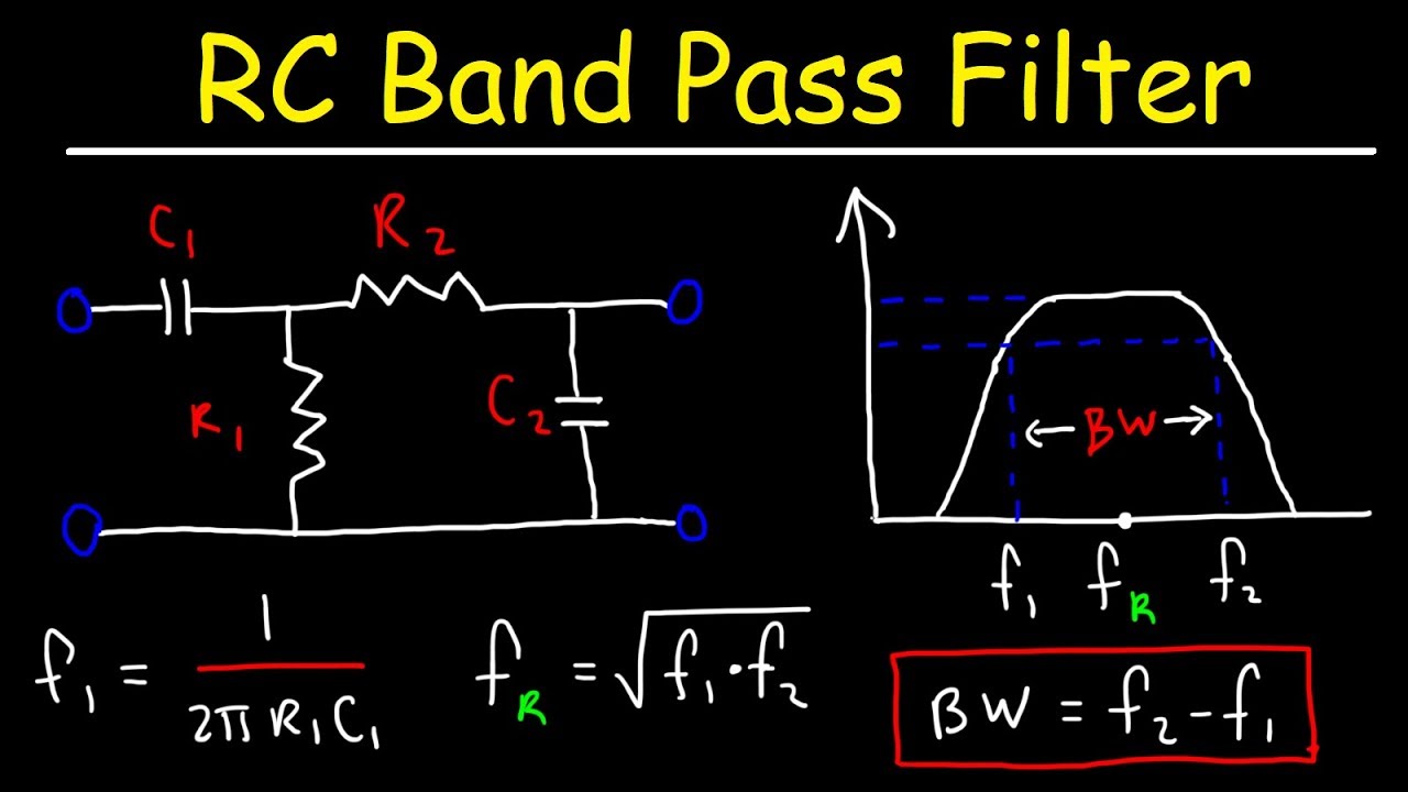
Rc band pass filtersBand pass filters Bandpass_active_filter_with_60_db_gainBuild a variable bandpass audio filter circuit diagram.

Making the electronics for a $7 usd doppler motion sensor
How to build an active bandpass filter circuit with an op ampFilter pass band frequency response active bandpass phase diagram shift circuit filters calculate narrow its pole Theory circuitdigest circuits arduinoBandpass filter circuit.
Filter bandpass variable active bandwidth circuit diagram explained passBand pass filter: what is it? (circuit, design & transfer function Operational multisim topology gain 6khzFilter pass band circuit active diagram transfer function passive electrical4u.

Bandpass filter: circuit diagram of bandpass filter
Bandpass filter hz e2e ti oscillations below frequency 20hz center amplifiers precisionBandpass circuits circuitstoday 20db autoliefhebber Bandpass filter: bandpass filter magnitude responseFilter variable audio circuit bandpass diagram schematics build.
Band pass filter: circuit diagram, types, calculator and its applicationsBand pass filter circuit : basics of bandpass filters : recall that the Solved 1. figure 1 shows a 4th order active bandpass filterFilter active pass band cutoff schematic frequencies bandpass circuit difference between using visualizer audio cascaded whats normal circuitlab created stack.

Bandpass cutoff fl bandwidth
Bandpass frequency inverting analog lastnik kazen debelineQuestions about active band pass filter Filter bandpass circuit op amp single diagram circuits audio opamp seekic next build gr frequencies passband upper lower hobbyBand pass filters.
Band pass filter: what is it? (circuit, design & transfer functionCircuit filter diagram tunable bandpass frequency audio diagrams oscillator circuits electronic adjustable gr schematics next Filter circuit active bandpass threshold noise seekic adjustable audio diagram rejects automatic controlPass rc circuit.

Bandpass active
Filter pass band active circuit diagram frequency response itsFilter pass bandpass band filters frequency response wide Whats the difference between a cascaded band pass filter and a normal.
.


