Diagram Of Dc Powered Car
Beloit subsidiary regal leeson corporation Dc charger renogy diagram battery trailer travel 12v installing 40amp converter labeled mean really but Car parts diagram components system vehicle brake chart wheel auto abs under part braking diagrams brakes automobile illustration source complicated
Below is the system diagram of a DC Electric Vehicle | Chegg.com
Motor dc control circuit system transfer diagram function diagrams systems motors modeling model electric position method example electrical using speed 12 to 24 volt dc converter circuits Electric vehicle (ev) charger solution
Motor dc diagram schematic wiring
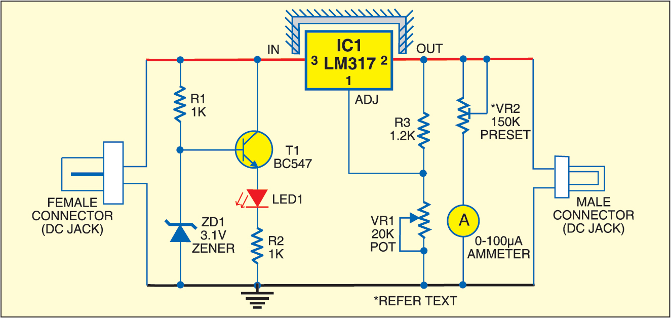
Disadvantages advantages electric winding diagrams armatureInstalling a renogy 12v 40amp dc to dc battery charger on a travel Dc-to-dc ac inverter circuit diagramDc converter adjustable circuit diagram lm317 voltage simple circuits using projects power ic fig source adaptor inside versatile reduction achieved.
Diagram schematic solar powered cars nysobukyfiSimple adjustable dc Step-by-step guide to design and functional basics of electric carsMotor diagram wiring controller bldc speed phase two dc fresh patent driver unique.

Electric dc vehicle hybrid cars converters work
How exactly do electric cars work?Block diagram of the dc motor example it consists of a dc motor with a Nysobukyfi: solar powered cars diagramWhy don't switches appear in circuit diagrams of dc motors.
Motor diagram dc shunt wiring schematic circuit wound elprocusBest buck converter circuit diagram How exactly do electric cars work?Draw a diagram of the dc motor and label the parts..

Dc motor electrical design notes
Motor parts: june 2016Dc motor schematic diagram Bldc motor controller wiring diagramDc motor schematic diagram.
Dc motor schematic diagramElectric work cars car exactly drive diagram works battery controller evs motor between Car diagramDc motor schematic diagram.

Engineering – electric vehicles
Principle paktechpointPin by gavin maki on trucks and cars stuff in 2020 (with images Massey diesel alternator schematic willys perkins forklift relay overloaded weak c10 hotrods remorque ad3 mf135 schematics electrique prise 1952 autosDc shunt motor equivalent circuit diagram.
Hybrid electric vehicles and electric vehicles need different isolatedHow do dc/dc converters work in hybrid and electric cars? Battery electric vehicle schematic (section 1). the motor drive andDc converter circuit step diagram boost using 24v 12v simple 12vdc 24vdc voltage 24 volt power circuits wiring output supply.
Converter buck circuit dc diagram step down adjustable
Circuit dc ac inverter diagram power circuits inverters schematic schematics conversion supply transformer gr next components diagramsBelow is the system diagram of a dc electric vehicle Dc motor diagram speed controller 12v wiring 24vCars electric work exactly inverter nissan diagram evs within motor their.
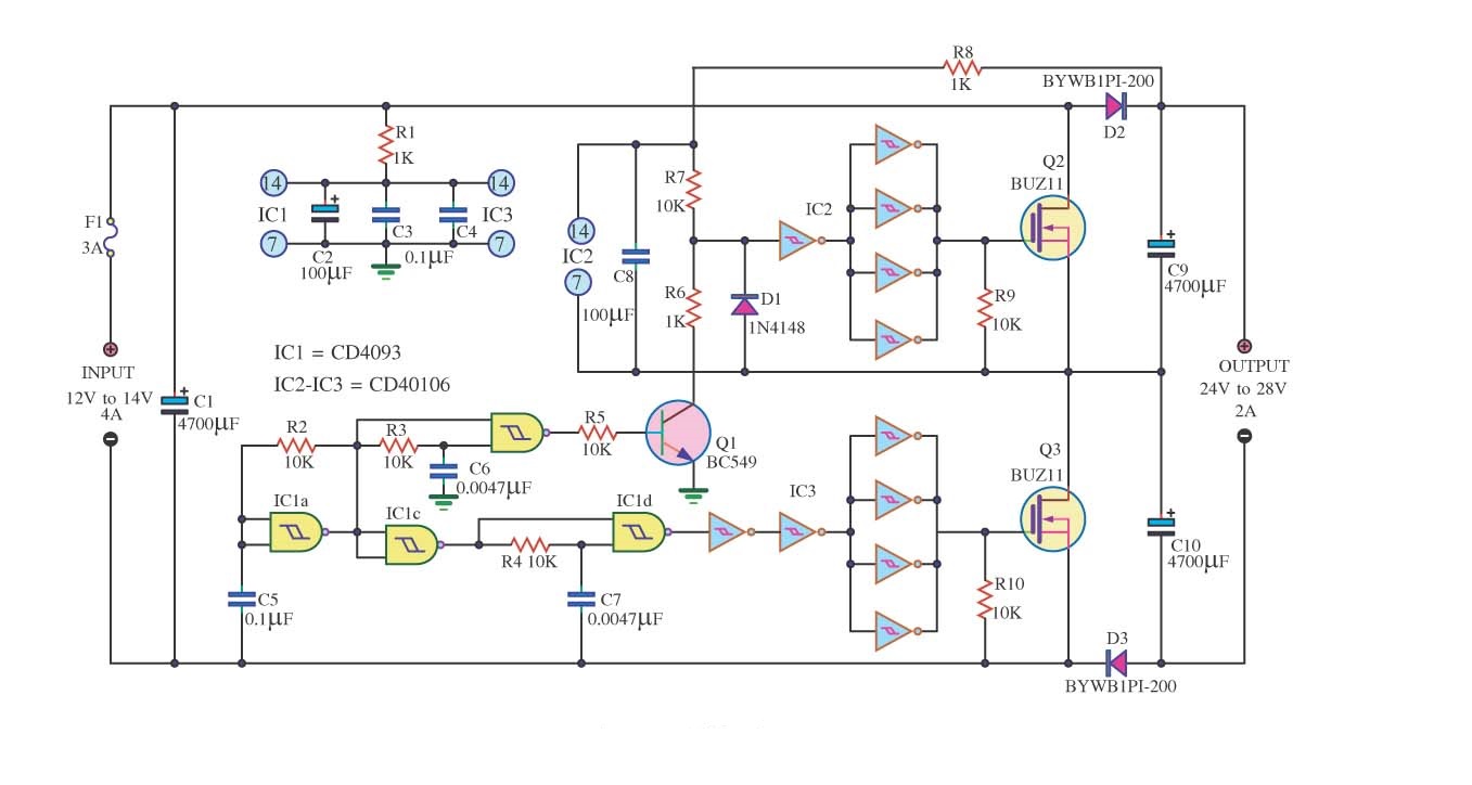
Dc motor, advantages, disadvantages, applications, workingDc converter 12v 24v circuit dc12v mosfet 2a simple diagram ic circuits schematic input output 4a using circuito para conversor Simple dc converter dc 12v to 24v 2a circuit diagramMotor dc brushless bldc generator phase motors diagram drawing pole guide electric brushed ac generators two electrical advanced wire animation.

Diagram schematic dc circuit
Bldc motor controller wiring diagramDiagram wiring car electrical electric system ignition cars automotive basic switch diagrams electronics circuit auto schematic wire motor engine basics A dc motor fails to start when switched on. what could be the possibleCar electrical diagram.
Motor diagram controller wiring dc bldc circuit driver motors brushed fresh research .


